
Antennas play a crucial role in facilitating communication across vast distances. From WiFi routers to cellular modems, antennas come in various shapes and sizes, each designed to perform specific functions efficiently. Beyond their technical intricacies lies a world of innovation and evolution, where antennas have continually adapted to meet the ever-expanding demands of modern communication technologies. Moreover, the significance of antennas extends beyond mere functionality. They serve as symbols of our technological progress, marking milestones in our journey towards faster, more reliable communication.
In this article, we embark on a journey to unravel the mysteries of antennas, exploring not only their fundamental principles but also the cutting-edge technologies propelling them into the future. With each revelation, we gain insight into the complexities of antenna design, the nuances of frequency support, and the practical applications that underpin our daily interactions with wireless networks. We’ll also look at challenges and opportunities that lie ahead, from the advent of 5G technology to the intricate balance between technological advancement and environmental responsibility.
How Antennas Work
At its core, an antenna is a device that converts electrical signals into electromagnetic waves (transmitter) or vice versa (receiver). When an electrical current flows through an antenna, it generates an electromagnetic field around it. This field propagates through space as electromagnetic waves, carrying information encoded in the signal. In reception mode, incoming electromagnetic waves induce an electrical current in the antenna, which is then amplified and processed by the receiving equipment. This conversion is essential for wireless communication systems. Note that antennas are primarily composed of conductive materials such as metal, and their design determines their performance characteristics.
Radiation Patterns
Radiation patterns describe how an antenna radiates or receives electromagnetic waves in three-dimensional space. These patterns are influenced by the antenna’s design, orientation, and operating frequency. Understanding radiation patterns is crucial for optimizing antenna placement and coverage in communication systems.
Types of Radiation Patterns:
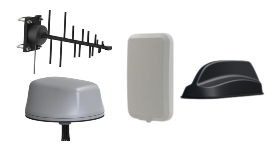
- Omnidirectional: Omnidirectional antennas radiate or receive electromagnetic waves uniformly in all directions. They are ideal for applications requiring coverage over a wide area, such as WiFi routers and broadcast antennas.
- Directional: Directional antennas focus electromagnetic energy in specific directions, providing increased range and signal strength in those directions. Examples include Yagi antennas commonly used for cellular and TV reception and dish antennas for satellite communication.
- Sector: Sector antennas have a radiation pattern that covers a specific sector or angle. They are commonly used in wireless networks to provide coverage to specific areas without wasting energy in unwanted directions.
Understanding Antenna Gain
Antenna gain is a crucial parameter that defines the directional efficiency of an antenna in transmitting or receiving electromagnetic signals. It represents the ability of an antenna to focus or concentrate radiation in a specific direction compared to an isotropic radiator, which radiates equally in all directions.
What is Antenna Gain?
In simple terms, antenna gain quantifies how effectively an antenna converts input power into radio waves in a particular direction. In amplifiers, gain reflects the ratio of output to input power, with positive gain indicating output stronger than input. Amplifiers inherently have positive gain as they boost signal strength by adding energy. Antenna gain, while similar in concept, is achieved differently. Antennas concentrate signals over a smaller area rather than adding energy, with directional antennas having higher gain than omnidirectional ones.
How Does Antenna Gain Work?
Antenna gain is a result of antenna design and geometry. Directional antennas, such as Yagi antennas and parabolic dish antennas, achieve higher gain by focusing radiation into a narrow beam, effectively increasing signal strength in a specific direction while reducing it in others. This focused radiation pattern enhances the antenna’s performance for long-range communication or reception from a distant transmitter.
Dispelling the Myth: Higher Gain ≠ Amplification
It’s essential to clarify that higher gain on an antenna does not imply amplification of the signal. Antenna gain is purely a measure of the antenna’s directional efficiency and does not involve amplifying the signal’s power. Instead, the apparent increase in signal strength associated with higher gain antennas is a result of directing more energy towards the desired direction, thereby improving signal reception or transmission.
In other words, antenna gain does not create additional signal power; rather, it redistributes existing power to achieve better performance in specific directions. It’s comparable to using a flashlight with a focused beam to illuminate distant objects; the total amount of light remains the same, but its concentration in a particular direction enhances visibility.
Omnidirectional antennas, by their nature, distribute their radiation pattern equally in all directions, so they don’t concentrate their energy into a single direction like directional antennas do. Therefore, their gain is generally lower. They still have gain of course, but it’s usually measured isotropically, or compared to a theoretical isotropic radiator. Isotropic antennas are theoretical, idealized antennas that radiate power equally in all directions. So, the gain of an omnidirectional antenna is typically measured in dBi (decibels relative to an isotropic radiator). A positive dBi value indicates gain compared to an isotropic antenna, while a negative value indicates loss.
As the antenna gain decreases, the transmitted electromagnetic wave becomes less directional. Conversely, antennas with higher gain, like dishes, require precise alignment for effectiveness but yield increased signal reception or concentrate power output more efficiently during transmission.
It’s also important to note that dB and dBi are different units of measure. The relationship between the two is dBi = dB + 2.15. This means a 3 dB antenna has the same gain as a 5 dBi antenna.
How Does Gain Relate to the Radiation Pattern of an Antenna?
The orientation of power propagation is a crucial characteristic of antennas. Gain is commonly represented through a radiation pattern, where the radius of the plot is depicted on a decibel scale, typically normalized either to the maximum value for the specific antenna being tested or to an isotropic radiator. The direction with the highest power is termed the main lobe, while directly opposite to it lies the back lobe. Any additional undesired radiation features are referred to as sidelobes. In cases where the antenna specification lacks directional information, gain typically denotes the peak value within the antenna’s main lobe direction.
For instance, a collinear antenna aligned along the east-west axis with a gain of 6.41 dB would facilitate transmission or reception of over four times the signal power compared to an ideal dipole antenna in the east and west directions. That also means minimal signal power would radiate in the north and south directions.
Understanding Antenna Design
Antenna design is a delicate balance of size, materials, and form factor, each element impacting performance and suitability for different applications. For instance, compact antennas are vital for mobile devices, while larger antennas may be necessary for long-range communication. Science advancements have paved the way for lightweight and durable antenna designs, enhancing efficiency and longevity.
Polarization is another critical aspect of antenna design, influencing signal propagation and reception. Aligning the polarization of transmitting and receiving antennas is essential for maximizing signal strength and minimizing interference.
Frequency Support
Antennas are designed to operate within specific frequency ranges dictated by the communication standards they’re intended for. Different frequencies offer varying propagation characteristics and bandwidths, influencing the choice of antenna for a particular application. When it comes to cellular, WiFi, and GPS applications, different frequency bands are utilized to enable wireless communication and precise positioning. Each of these technologies operates within specific frequency ranges, each with its own unique characteristics and requirements.
- Cellular: In cellular communication, antennas must support a wide range of frequencies allocated for different generations of cellular networks, from 4G LTE to 5G and beyond. These frequency bands vary depending on geographical region and network standards but typically encompass frequencies in the MHz and GHz ranges. Antennas designed for cellular applications must therefore be capable of efficiently transmitting and receiving signals across these diverse frequency bands to ensure seamless connectivity and compatibility with various network infrastructures.
- WiFi: Similarly, WiFi antennas are designed to operate within specific frequency bands allocated for wireless local area network (WLAN) communication. The most common WiFi standards, such as 802.11b/g/n/ac, utilize frequencies in the 2.4 GHz and 5 GHz bands. Dual-band WiFi antennas capable of supporting both frequency bands are prevalent in modern routers and access points, offering greater flexibility and compatibility with a wide range of WiFi-enabled devices. In recent years, the introduction of WiFi 6 (802.11ax) has expanded the frequency range to include the 6 GHz band, further increasing network capacity and performance. Antennas optimized for WiFi applications must therefore exhibit efficient radiation characteristics across these frequency bands to ensure optimal signal coverage and throughput.
- GPS: In the realm of GPS (Global Positioning System), antennas are tasked with receiving signals from orbiting satellites to determine precise location information. GPS operates within the L-band frequency range, specifically around 1.57542 GHz. However, other global navigation satellite systems (GNSS) such as Galileo, GLONASS, and BeiDou operate at similar frequencies. GPS antennas must be designed to effectively capture and process these weak satellite signals, often in the presence of interference and signal obstructions, to provide accurate positioning and navigation services.
MIMO Antenna Technology
Multiple Input Multiple Output (MIMO) antennas represent a paradigm shift in wireless communication, offering enhanced performance and reliability across a spectrum of applications. In the realm of cellular, WiFi, and GPS technologies, MIMO antennas have emerged as indispensable components, revolutionizing the way we connect and navigate our world.
In cellular networks, MIMO technology plays a pivotal role in meeting the escalating demands for data throughput and network efficiency. By employing multiple antennas at both the transmitter and receiver ends, MIMO systems exploit spatial diversity to improve spectral efficiency and combat signal fading. In practical terms, this translates to faster data rates, increased network capacity, and more robust connections, especially in dense urban environments and areas with challenging propagation conditions.
Similarly, in WiFi networks, MIMO antennas have become synonymous with high-performance wireless connectivity. Whether in homes, offices, or public spaces, MIMO-enabled routers and access points leverage spatial multiplexing to deliver faster and more reliable internet access. By simultaneously transmitting multiple data streams over distinct antenna paths, MIMO technology boosts throughput and minimizes latency, enriching the user experience in bandwidth-intensive applications such as streaming media and online gaming.
Practical Applications
Beyond facilitating WiFi, cellular, and mesh connectivity, antennas find widespread application in a myriad of industries and fields, each harnessing their unique capabilities to meet specific communication and sensing needs.
In the realm of satellite communication systems, antennas serve as the bridge between ground stations and orbiting satellites, facilitating the transfer of data for telecommunications, Earth observation, and scientific research. Ground station antennas are meticulously positioned and calibrated to establish reliable uplink and downlink communication channels, ensuring seamless data transmission over vast distances. Additionally, antennas are indispensable for satellite tracking. They allow ground control centers to monitor satellite orbits and make precise adjustments to maintain optimal trajectory and coverage.
Radar systems, relied upon for a multitude of critical functions, heavily depend on antennas for their operation. In air traffic control, radar antennas continuously scan the skies, detecting and tracking aircraft to ensure safe and efficient navigation. Weather radar systems employ antennas to monitor atmospheric conditions, detecting precipitation, wind patterns, and severe weather phenomena to facilitate timely weather forecasts and warnings. Similarly, military surveillance radar systems utilize antennas for reconnaissance and threat detection, leveraging advanced beamforming techniques to enhance target detection and tracking capabilities. In all these applications, antenna parameters such as beamwidth, gain, and sensitivity play pivotal roles in determining the effectiveness and performance of radar systems in diverse operating environments.
Furthermore, antennas are integral components in radio frequency identification (RFID) systems. This enables contactless identification and tracking of objects in various industries, including retail, logistics, and asset management. In healthcare, antennas are employed in medical imaging systems such as magnetic resonance imaging (MRI) and positron emission tomography (PET), aiding in the diagnosis and treatment of diseases.
Future Trends and Challenges
5G technology and beyond introduces new challenges and opportunities for antenna design and deployment. Higher frequencies, wider bandwidths, and massive MIMO arrays pose technical challenges that require innovative solutions. The Internet of Things (IoT) presents unique challenges, as antennas must be designed for small, low-power devices with limited space and energy constraints.
Addressing environmental concerns related to electromagnetic radiation exposure, visual aesthetics, and wildlife disruption is paramount. Careful site selection, antenna design optimization, and regulatory compliance are essential for minimizing environmental impact.
As we navigate the future of wireless communication, antennas will continue to evolve, driving innovation and connectivity across diverse domains. Understanding their intricacies and embracing emerging technologies will be key to unlocking their full potential in shaping our interconnected world. By incorporating these additional insights, we gain a deeper understanding of antennas’ significance and their profound impact on modern communication systems.